

Converting an M1937 Fire Unit to Propane
Conversion Procedure (Part 5)
By David Jarvela
Click on the thumbnail for a larger view of each photograph.
Start by screwing the 3/8"x1-1/4" blk. nipple into the 3/8" needle valve on the outlet side (the valve should be marked with gas flow direction).
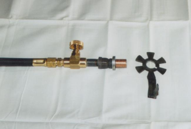 |
| The burner assembly should look like this before proceeding. The propane hose is connected in the photo, which will be covered later on. |
Remember to use pipe thread compound on the male threads of each fitting you assemble. I will refer to it as pipe dope from here on in. Use enough! Make sure it oozes out of the threads after they are tightened with the wrenches. Use a rag to wipe off the excess pipe dope that comes out. The dope is important to seal the threads from gas leakage. Use a vise or adjustable (Crescent) wrench to hold the valve body when you tighten the nipple.
Thread the 3/8"x1/4" blk. reducing coupling onto the 3/8" nipple. Then start the 1/4" close nipple by hand into the 1/4" blk. coupling. Place two of the flat washers onto the nipple. Then thread the 1/4" nipple into the 1/4" female end of the reducing coupling.
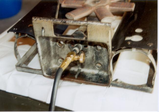 |
| The completed assembly. The housing in which the propane hose feeds held the gauges and valves on the gasoline fire unit. |
Remember, washers come in varying thicknesses and depending on where you buy your washers you may have to use more or fewer than I did. You may also have to drill them out to allow the nipple to go through them. Tighten this assembly together at this time. Use the pipe wrenches on the couplings only to do this. Do not apply the wrenches to the close nipple. The copper tube can now be slid onto the 1/4" coupling.
Slide the air shutter over the assembly up to the washers. Place this whole unit in the flame valve assembly tube in the panel.
The ends of the copper tube and the 1/4" coupling should be flush with the end of the flame valve assembly tube. If not you may have to add or remove a washer, or use thinner or thicker washers or a combination of both.
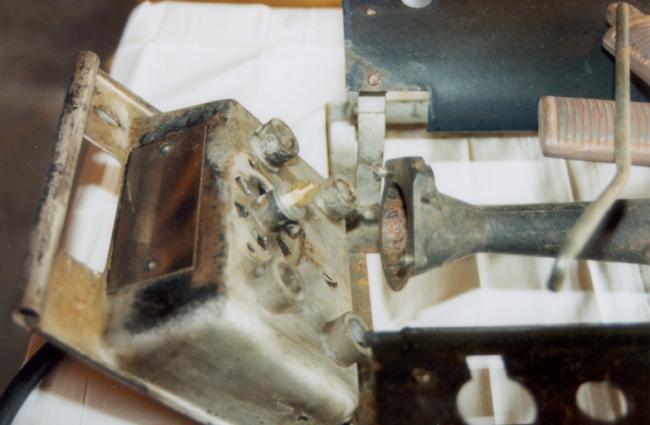 |
| The mixing chamber is the cast iron tube in the middle right section of the photograph. Note the orifice in the center of the instrument housing. |
Apply pipe dope to the 1/4" npt male threads of the orifice. Slide two washers over the threads and screw by hand into the 1/4" blk. coupling. Using adjustable wrenches (one holding the valve and the other the orifice) tighten the orifice into the 1/4" coupling.
Make sure you dont over tighten and strip the brass threads of the orifice, or that the air shutter cant move. My burners work best with the air shutter open all the way. You will notice that assemblage in this manner effectively closes off the mixing chamber opening that the vapor tube on the generator inserted into.
Articles:
David Jarvela is a native of White Pine, Mich. He currently lives in Hoyt Lakes, Minn. Questions or comments? E-mail him at: Yooper_in_Mn@yahoo.com
Copyright © 2000 by David Jarvela. All rights reserved. Used with permission.
October 2000
| Bulletin Board | Keyword Search |
| Bookstore | Links |
| About Us | Recent Additions |
![]()